Introduction
Purchasing machinery is only one stage of building a production plant. Equipment procurement confirms capacity, specification, and vendor scope — it does not confirm that the plant will run.
Every machine arrives as an independent unit, engineered to its own vendor standard, with its own utility loads, footprint, and control logic. Without deliberate process integration, these units remain a collection of assets rather than a production system.
When equipment, process flow, utilities, layout, and logistics are not coordinated, common outcomes include:
- Capacity mismatches between upstream and downstream equipment
- Utility shortfalls or oversized utility infrastructure
- Piping and cable routing conflicts discovered during installation
- Material-flow bottlenecks that reduce actual plant throughput
- Delayed commissioning due to late-stage interface corrections
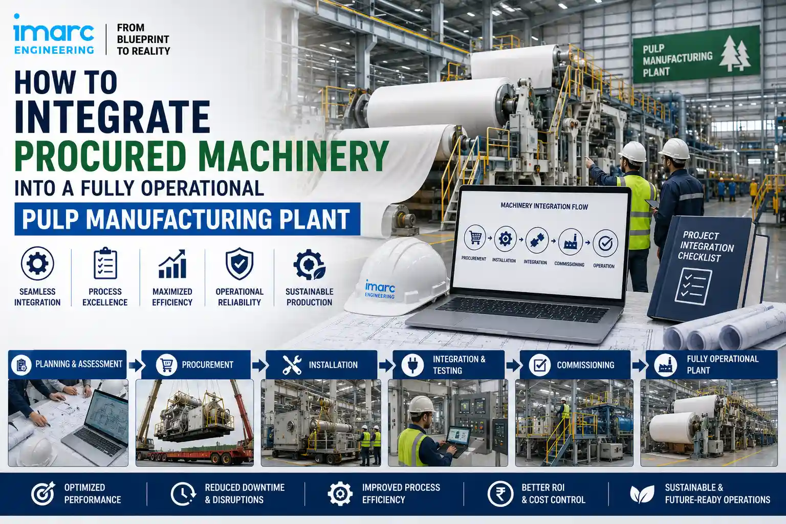
Machinery integration is the engineering work that closes this gap — before installation, not after. This article outlines a structured, engineering-led approach to integrating procured machinery into a fully functional pulp manufacturing plant.
What Does Machinery Integration Mean in a Pulp Manufacturing Plant?
Machinery integration means engineering all procured equipment to function as one coordinated production system.
It covers:
- Equipment-to-equipment integration — matching capacities, inlet/outlet conditions, and operating parameters
- Process sequence — confirming the correct production order across pulping, washing, screening, and pulp-sheet forming stages, with additional treatment stages where applicable
- Material flow — pulp, fibre, liquor, and reject movement between stages
- Utilities — power, water, steam, compressed air, and drainage supplied to each machine
- Piping and instrumentation — physical connections and control signal paths
- Electrical and control interfaces — power distribution and automation architecture
- Maintenance and access requirements — space for servicing, inspection, and replacement
- Commissioning coordination — the sequence in which systems are tested and started
Integration is not a single task. It is a layer of engineering that sits between procurement and installation.
Why Purchased Machinery Can Still Create Integration Problems
Procured equipment is typically designed to a specification, not to a specific plant. This creates predictable integration risks.
- Equipment interface differences — connection sizes, control protocols, or utility ratings that don’t align across vendors
- Capacity mismatches — one machine outperforming or underperforming its neighboring stage
- Poor equipment positioning — units placed without accounting for flow direction, access, or future expansion
- Utility connection issues — inconsistent voltage, pressure, or supply points across vendor packages
- Piping and access conflicts — routing that obstructs maintenance doors, walkways, or crane paths
- Material-flow inefficiencies — layouts that create unnecessary handling steps or queuing
- Maintenance and access problems — insufficient clearance for routine servicing
- Commissioning delays — interface issues surfacing only during start-up, when correction is costliest
These issues are rarely caused by faulty equipment. They are caused by the absence of a coordinated integration plan before installation begins.
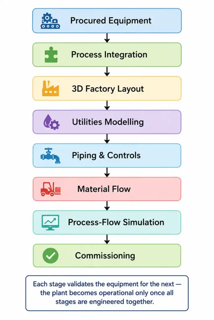
Step-by-Step Process for Integrating Procured Machinery
Step 1: Collect Equipment and Vendor Data
Before any layout or process work begins, consolidate vendor data for every machine:
- Dimensions and weight
- Rated capacity
- Power requirements
- Utility requirements (water, steam, air)
- Inlet/outlet connection sizes and nozzle locations
- Instrumentation and control interfaces
- Operating parameters (pressure, temperature, consistency)
- Maintenance requirements
- Vendor general arrangement (GA) drawings
Incomplete vendor data at this stage is the most common cause of downstream rework.
Step 2: Develop the Process Flow
Map the production sequence across the full plant:
- Confirm upstream/downstream dependencies between stages
- Define material flow direction through pulping, washing, screening, and pulp-sheet forming stages
- Identify where process continuity depends on buffer or intermediate storage
- Flag any stage where procured capacity doesn’t match adjacent stages
Step 3: Prepare the Mass Balance
A mass balance validates that material quantities are consistent across the plant:
- Raw material/feedstock input
- Water and process liquor volumes
- Fibre/pulp flow through each stage
- Rejects and process losses
- Final product output
- Capacity relationships between consecutive machines
Without a mass balance, capacity mismatches often remain hidden until commissioning.
Step 4: Develop the 3D Factory Layout
The 3D factory layout translates vendor drawings and process data into a physical plant arrangement:
- Equipment positioning based on process sequence and flow direction
- Space utilization across production and storage areas
- Maintenance and operator access around each machine
- Installation access for cranes and heavy equipment
- Piping and cable routing paths
- Structural coordination with building and foundation design
- Clash detection between equipment, piping, structure, and services
Step 5: Integrate Utilities
Utility requirements from each machine are consolidated into a plant-wide system:
- Electrical power distribution
- Process water supply
- Steam or thermal utilities, where applicable
- Compressed and instrument air
- Drainage
- Effluent and waste handling
- Utility routing coordinated with the layout
Step 6: Integrate Piping and Instrumentation
This step connects equipment physically and functionally:
- Process piping between production stages
- Utility piping for water, steam, and air
- Pumps and valves sized to actual flow conditions
- Instruments and control loops
- Cable and instrument routing
- Coordination against the P&ID for consistency
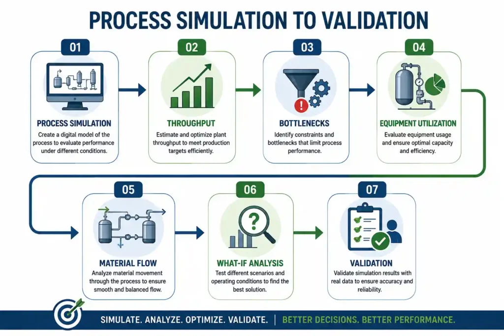
Step 7: Simulate Process and Material Flow
Process-flow simulation validates the plant before physical commitment:
- Throughput against design capacity
- Equipment utilization rates
- Bottlenecks and queue points
- Material movement patterns
- What-if scenarios for capacity or sequencing changes
- Capacity validation across the full production line
How 3D Factory Layout Supports Machinery Integration
A coordinated 3D factory layout helps validate equipment placement and identify spatial conflicts before installation. It supports:
- Equipment positioning based on process flow
- Space and access verification
- Maintenance and installation access
- Piping and cable route coordination
- Clash detection across mechanical, structural, and electrical systems
- Material movement planning
Identifying these conflicts in the digital model allows the project team to address them before equipment is installed.
Why Process-Flow Simulation Matters Before Commissioning
Process-flow simulation tests how the plant will actually perform, not just how it is designed to perform.
It helps validate:
- Throughput against rated capacity
- Bottlenecks between production stages
- Equipment utilization under real operating conditions
- Material-flow behavior across the line
- Different production scenarios and demand levels
- Capacity limits before physical changes are required
- Operational decisions made on data, not assumptions
Utilities Integration in a New Pulp Plant
Individual machines specify their own utility demand. Plant-wide integration consolidates these into one coordinated system.
Key considerations:
- Utility requirements of each piece of equipment
- Consolidated utility demand across the plant
- Distribution routing coordinated with layout
- Peak demand periods and load variation
- Connection points for each equipment package
- Drainage and waste system integration
| Utility | Integration Focus |
| Electrical Power | Load consolidation, distribution routing |
| Process Water | Supply volume, connection points |
| Steam/Thermal | Demand consolidation, distribution |
| Compressed Air | Instrument and process air supply |
| Drainage/Effluent | Waste routing, treatment interface |
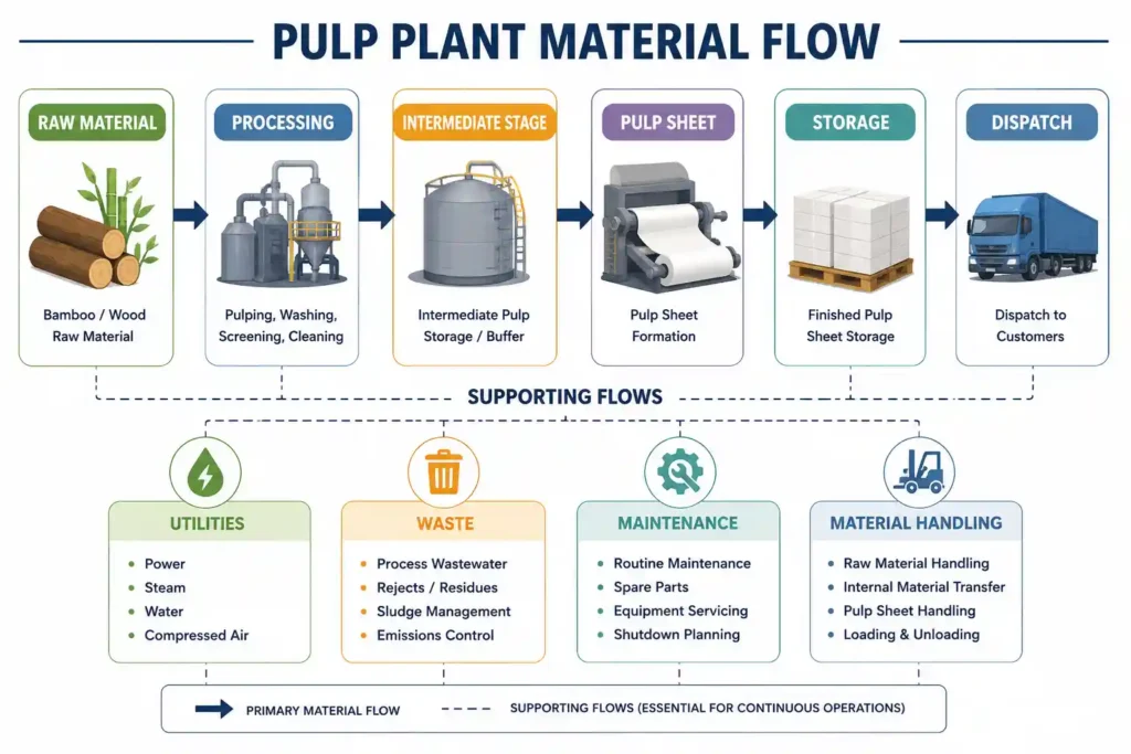
Logistics and Material-Flow Integration
Logistics integration ensures that raw materials, intermediate materials, finished pulp sheets, waste, and handling equipment move through the plant without creating avoidable congestion.
Integration covers:
- Raw material receiving and storage
- Internal material movement between process stages
- Intermediate storage and buffer points
- Finished product movement
- Waste and reject movement
- Material-handling routes and equipment
- Storage and dispatch coordination
- Identification of congestion points
- Logistics simulation to test material movement under real production conditions
How to Identify Integration Gaps Before Commissioning
A practical checklist before installation proceeds:
- Are equipment interfaces (connections, protocols) confirmed across all vendors?
- Does the process flow reflect actual upstream/downstream dependencies?
- Has the mass balance been validated across all stages?
- Are utility demands consolidated and matched to supply capacity?
- Is piping routed without access or structural conflicts?
- Are electrical connections mapped to confirmed load requirements?
- Is instrumentation aligned with the control architecture?
- Has the 3D layout been checked for clashes?
- Has material flow been tested for bottlenecks or congestion?
- Are capacity relationships between stages verified?
- Is the commissioning sequence defined and agreed?
What Should Be Validated Before Equipment Installation?
Before physical installation begins, engineering validation should confirm:
- Equipment arrangement matches the approved layout
- Process sequence aligns with the mass balance
- Utility demand matches available supply
- Piping connections match vendor and P&ID requirements
- Electrical connections are load-verified
- Instrumentation is mapped to the control system
- Material-handling routes are clear and sized correctly
- Maintenance access is preserved around all equipment
- Safety and emergency access routes are unobstructed
- Commissioning requirements are documented and sequenced
From Engineering Integration to Commissioning
Once integration is validated, the plant moves toward physical readiness:
- Installation readiness confirmation
- Mechanical checks on equipment and structural supports
- Piping checks against P&IDs
- Electrical and instrumentation checks
- Controls verification across automation systems
- System and subsystem testing
- Start-up sequencing
- Performance validation against design parameters
- Process optimization based on actual operating data
Engineering integration reduces the number of unknowns entering commissioning — which is where issues are most expensive to resolve.
Key Takeaways
- Procuring machinery does not automatically create an operational plant.
- Integration requires coordinated engineering across process, layout, utilities, piping, and controls.
- Vendor data collection is the foundation for accurate integration work.
- Mass balance and process-flow mapping validate capacity relationships between stages.
- 3D factory layout identifies spatial and access conflicts before construction.
- Process-flow and logistics simulation validate throughput and material movement before commissioning.
- A structured integration checklist reduces the risk of late-stage commissioning delays.
How IMARC Engineering Can Support Pulp Plant Integration
Integrating procured machinery into a functioning pulp manufacturing plant involves multiple engineering disciplines working from a shared, coordinated model.
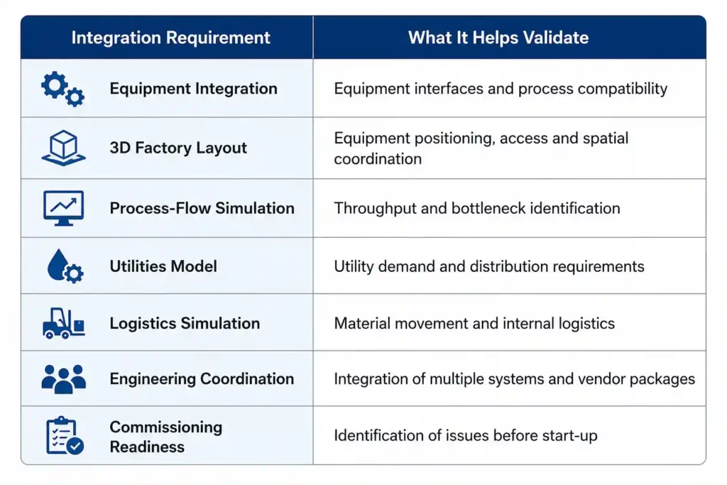
IMARC Engineering supports manufacturers, plant owners, and project teams with the engineering work required to bring procured equipment together into one operational system, including:
- 3D factory layout development for equipment positioning, access, and spatial coordination
- Process-flow modelling and simulation to validate throughput and identify bottlenecks
- Utilities modelling to consolidate and route plant-wide utility demand
- Material-flow and logistics simulation to test internal movement and identify congestion points
- Equipment integration support across multiple vendor packages
- Engineering coordination between mechanical, electrical, piping, and structural disciplines
- Commissioning readiness support, helping identify integration gaps before start-up
This engineering work is applied based on each plant’s specific equipment, layout, and process requirements. Manufacturers planning machinery integration or plant expansion can discuss their equipment, layout, and process requirements with IMARC Engineering.
Need help integrating your procured machinery into a fully operational plant?
Talk to IMARC Engineering for 3D layout, process simulation, utilities, and logistics integration: https://www.imarcengineering.com/contact?service=plant-layout-and-process-flow-design
Conclusion
Integrating procured machinery into a pulp manufacturing plant requires more than installing individual equipment packages. The process must be coordinated across equipment interfaces, process flow, utilities, piping, controls, layout, and material movement to create a system that can operate as intended.
A structured engineering approach allows integration gaps, capacity constraints, layout conflicts, and material-flow issues to be identified before they become installation or commissioning problems. By validating the plant digitally and coordinating the different engineering disciplines before start-up, manufacturers can move from procured machinery to an integrated, operational production system with greater engineering confidence.
Contact Us:
IMARC Engineering
Phone: +91-120-433-0800
Email: sales@imarcengineering.com
India: C-130, Sector 2, Noida, Uttar Pradesh 201301
LinkedIn: https://www.linkedin.com/showcase/imarc-engineering/
About the Author